NUMBER #
Overview #
In DWGSeeCAD, the NUMBER command opens the Number annotation dialog for creating sequential circular number tags. You can define the insertion position of the number circle, starting sequence number, text height, rotation angle, and choose whether to add a leader line. It also supports a special mode to place number annotations automatically in the middle of selected line segments.
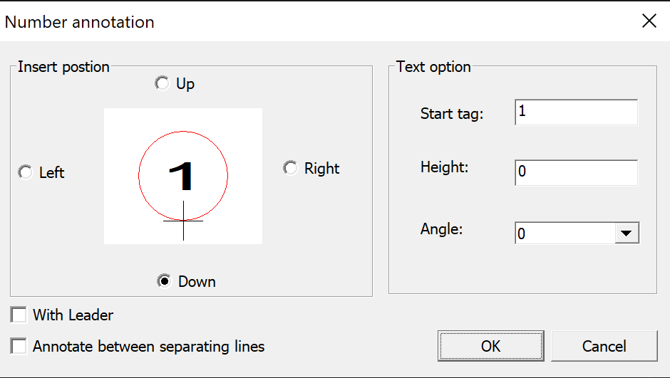
Dialog Settings #
- Insert position: Sets the relative position of the numbered circle against the pick point. Options: Up / Down / Left / Right.
- Start tag: Defines the initial sequence number for the annotation, increments automatically for subsequent tags.
- Height: Sets the text height of the number inside the circle. A value of 0 uses the default text height.
- Angle: Sets the rotation angle of the number text.
- With Leader: Adds a leader line connecting the circular tag to the picked point.
- Annotate between separating lines: Automatically inserts the sequential number annotation at the midpoint of selected line segments.
Usage Notes #
- Each newly placed number tag will automatically increment from the Start tag value.
- When Annotate between separating lines is enabled, the program identifies line segments and places the number mark at the segment center.
- Insert position controls which side of the pick point the circular number symbol appears on.
- Uncheck With Leader if you only need a circled number without an extension leader.
Application Scenarios #
Use NUMBER for part markers, component callouts, reference tags, revision marks, and numbering items on assembly drawings, electrical schematics, P&ID diagrams and structural details. The mid-line annotation mode is convenient for marking segment numbers on pipelines, wiring and dividing lines.


