Skip to content

DWGSee CAD Support

  • Home
  • Download
  • Articles
  • User Guide
  • Contact
DWGSee CAD Support

What's New

7
  • New Features in DWGSee CAD 2027
    • Aligh entities
    • Extract Dimension
    • SCRIPT
    • UNION(Command)
    • SUBTRACT (Command)
    • MASSPROP
    • Rename

Get Started

4
  • Command Line List
  • Main Features
  • System Requirements
  • Welcome to DWGSee CAD

Have You Tried?

6
  • How to Extract Dimensions from Engineering Drawings
  • How to isolate objects
  • How to use Design Center in DWGSee CAD
  • How to merge lines/arcs to one ployline
  • How to Draw Arrows in DWGSee CAD
  • How to Select Objects Based on Shared Properties?

User Guide

117
  • User Interface
    • GRID
  • Manage Drawing Files
    • Ucsicon
    • ISOLATEOBJECTS (Command)
    • UNISOLATEOBJECTS (Command)
    • HIDEOBJECTS (Command)
    • Units
    • Create a new drawing
  • Create Objects
    • BLEND
    • Hatch
    • Ellipse
    • Circle
    • Multiline
    • Spline
    • Point
    • XLINE
    • UNION(Command)
    • SUBTRACT (Command)
    • INTERSECT(Command)
    • Arc
    • Rectangle
    • Polygon
    • Polyline
    • Line
    • Create Text
      • TEXTABOVELINE
      • ARCTEXT
      • STYLE
    • Create Curved and Closed Geometry
      • SOLID
      • About Donuts
        • Donut
      • About Regions
        • Region
    • Create Linear and Reference Geometry
      • ExLine
      • MLSTYLE
      • TangentLine
  • Reference External Files and Data
    • ADCENTER
    • InsFromDWG
    • INSBLKDESIGNBIND
    • DWFATTACH
  • Defining Blocks
    • STATBLK
    • WBLOCK
    • About Purging Unreferenced Layers, Blocks, and Style Definitions
      • PURGE
  • Modify Objects
    • DIMSYMDRIVER
    • SHAFTUNDERCUT
    • HOLEUNDERCUT
    • HOLECHAMFER
    • SHAFTCHAMFER
    • BLKREPLACE
    • TXTEXP
    • IMAGECLIP
    • VPCLIP
    • LINESTOPL
    • DCANGULAR
    • DIMALIGN
    • DIMOBLIQUE
    • DIMDRIVER
    • CHAMFER
    • EXTEND
    • TRIM
    • Pedit
    • Mledit
    • Fillet
    • Copy
    • Scale
    • Array
    • Mirror
    • PURGE
    • Duplicate and Array Objects
      • Patharray
      • Offset
      • About Copying Objects
        • NCOPY(Command)
    • Remove Objects and Object Segments
      • Erase
      • Break
      • Join
      • About Correcting Mistakes
        • Overkill
        • OOPS
    • Change General Object Properties
      • SELECTSIMILAR
      • CANNOSCALE
      • Draw order
      • Linetype
      • Layer
      • How to Change the Color of Selected Objects?
      • LIST
      • About Object Properties
        • MATCHPROP
    • Editing Complex Objects
      • XCLIP
      • DDPTYPE
      • EDITTOL
      • EXPLODE
    • Change the Size and Length of Objects
      • Lengthen
      • EXTEND
      • TRIM
    • Move and Rotate Objects
      • Aligh entities
      • Align
      • Rotate
      • Stretch
      • Move
  • Control Drawing Views
    • REGEN
    • ZOOM
    • PAN
  • Control Precision with Drafting Aids
    • SNAP
    • LIMITS (Command)
  • Add Hatches, Fills, Tables, and Revision Clouds
    • GRADIENT
    • Wipeout
  • Create Notes, Labels, and Leaders
    • TEXTALIGN
    • Extract Dimension
    • ANNOALLVISIBLE (System Variable)
  • Dimension Objects
    • DIMCHAMFER
    • SCALEPART
    • REVC
    • DIMSTYLE
    • DIMCONTINUE
    • DIMJOGGED
    • NUMBER
    • DIMALIGNED
    • DIMBASELINE
    • TOLERANCE
    • CenterLine
  • Tools
    • STATBLK
    • STATTBLK
    • Extract table
    • PLDATA

License

1
  • End-User License Agreement
View Categories
  • DWGSee CAD
  • Support
  • Have You Tried?
  • How to Extract Dimensions from Engineering Drawings

How to Extract Dimensions from Engineering Drawings

0:00 / 2:53

For quality engineers and manufacturing teams, preparing full-dimension inspection reports and first article inspection (FAI) documents is one of the most repetitive, time-consuming tasks. Traditionally, engineers manually identify every dimension, tolerance and GD&T feature on a drawing, add balloon callouts one by one, then copy all values into inspection spreadsheets. A moderately complex drawing often takes 2–4 hours to finish, with constant risks of missed dimensions, duplicate numbering and human typing errors.

DWGSeeCAD’s Extract Dim function is designed to solve this pain point. It directly reads native dimension objects inside DWG files, automatically generates sequential balloon callouts, and builds a structured inspection checklist in seconds. No manual transcription, no error-prone OCR for static images.
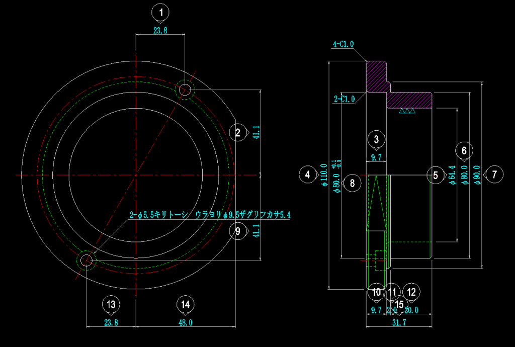
Automatically add bubble annotations after box selection
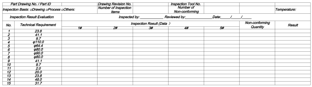
Automatically output according to the template, corresponding one-to-one with the feature list, eliminating the need for manual organization (templates can be customized)

How the Extract Dimension Workflow Runs #

The whole process is simple and CAD-native:

  1. Open your target DWG drawing in DWGSeeCAD. Launch the tool via the menu Tools > Extract Dim, or enter the Extractdim command in the command line.
  2. Drag to select the drawing area containing dimensions you need to inspect, then right-click to start recognition.
  3. Review the preview table of extracted dimensions and tolerances. Adjust balloon text height as needed to match your drawing style.
  4. Confirm the operation. The tool automatically inserts numbered balloons linked to each dimension, and generates an inspection table on a new layout named Inspection 0.

Core Capabilities #

  • Select‑and‑Recognize: Select any region on the drawing to extract only the dimensions you require, instead of processing the whole drawing blindly.
  • Customizable Balloon Size: Adjust balloon text height and style to align with your company drafting standards.
  • Auto‑sequenced Balloon Numbering: Automatically assign continuous unique numbers for each inspection characteristic.
  • Drawing‑Driven Checklist Sync: Inspection lists refresh automatically when balloons are added or removed on drawings. Changes made to CAD balloon numbering propagate to your inspection checklist. Updates only flow from the drawing to the inspection table; edits inside the checklist will not write back to the CAD drawing.
  • One‑click Full‑Dimension Inspection Report Export: Export the complete inspection table ready for PPAP, AS9102 FAIR and in-process quality control.
  • Vector‑based PDF Export: Save the ballooned drawing and inspection sheet as vector PDF for clean sharing with customers and suppliers.

Built for Compliance-Centric Manufacturing #

Automotive, aerospace, medical device, mold and heavy equipment industries all require traceable, cross-referenced inspection records. IATF 16949, PPAP and AS9102 standards demand clear one-to-one mapping between ballooned callouts and inspection records.

DWGSeeCAD Extract Dim keeps the data linked to native CAD dimension entities. It retains nominal values, tolerances and GD&T information, helping your quality team deliver audit-ready inspection documents while cutting prep time from hours down to less than 30 seconds.

Wrap Up #

Instead of manually ballooning and transcribing dimensions, let DWGSeeCAD handle the extraction and numbering. The Extract Dim function streamlines your quality workflow, reduces human error, and helps your team focus on actual measurement and validation rather than repetitive paperwork.

Share This Article :

  • Facebook
  • X
  • LinkedIn
  • Pinterest
Table of Contents
  • How the Extract Dimension Workflow Runs
  • Core Capabilities
  • Built for Compliance-Centric Manufacturing
  • Wrap Up

© 2026 DWGSee CAD Support

  • Home
  • Download
  • Articles
  • User Guide
  • Contact