Skip to content

DWGSee CAD Support

  • Home
  • Download
  • Articles
  • User Guide
  • Contact
DWGSee CAD Support

What's New

7
  • New Features in DWGSee CAD 2027
    • Aligh entities
    • Extract Dimension
    • SCRIPT
    • UNION(Command)
    • SUBTRACT (Command)
    • MASSPROP
    • Rename

Get Started

4
  • Command Line List
  • Main Features
  • System Requirements
  • Welcome to DWGSee CAD

Have You Tried?

6
  • How to Extract Dimensions from Engineering Drawings
  • How to isolate objects
  • How to use Design Center in DWGSee CAD
  • How to merge lines/arcs to one ployline
  • How to Draw Arrows in DWGSee CAD
  • How to Select Objects Based on Shared Properties?

User Guide

117
  • User Interface
    • GRID
  • Manage Drawing Files
    • Ucsicon
    • ISOLATEOBJECTS (Command)
    • UNISOLATEOBJECTS (Command)
    • HIDEOBJECTS (Command)
    • Units
    • Create a new drawing
  • Create Objects
    • BLEND
    • Hatch
    • Ellipse
    • Circle
    • Multiline
    • Spline
    • Point
    • XLINE
    • UNION(Command)
    • SUBTRACT (Command)
    • INTERSECT(Command)
    • Arc
    • Rectangle
    • Polygon
    • Polyline
    • Line
    • Create Text
      • TEXTABOVELINE
      • ARCTEXT
      • STYLE
    • Create Curved and Closed Geometry
      • SOLID
      • About Donuts
        • Donut
      • About Regions
        • Region
    • Create Linear and Reference Geometry
      • ExLine
      • MLSTYLE
      • TangentLine
  • Reference External Files and Data
    • ADCENTER
    • InsFromDWG
    • INSBLKDESIGNBIND
    • DWFATTACH
  • Defining Blocks
    • STATBLK
    • WBLOCK
    • About Purging Unreferenced Layers, Blocks, and Style Definitions
      • PURGE
  • Modify Objects
    • DIMSYMDRIVER
    • SHAFTUNDERCUT
    • HOLEUNDERCUT
    • HOLECHAMFER
    • SHAFTCHAMFER
    • BLKREPLACE
    • TXTEXP
    • IMAGECLIP
    • VPCLIP
    • LINESTOPL
    • DCANGULAR
    • DIMALIGN
    • DIMOBLIQUE
    • DIMDRIVER
    • CHAMFER
    • EXTEND
    • TRIM
    • Pedit
    • Mledit
    • Fillet
    • Copy
    • Scale
    • Array
    • Mirror
    • PURGE
    • Duplicate and Array Objects
      • Patharray
      • Offset
      • About Copying Objects
        • NCOPY(Command)
    • Remove Objects and Object Segments
      • Erase
      • Break
      • Join
      • About Correcting Mistakes
        • Overkill
        • OOPS
    • Change General Object Properties
      • SELECTSIMILAR
      • CANNOSCALE
      • Draw order
      • Linetype
      • Layer
      • How to Change the Color of Selected Objects?
      • LIST
      • About Object Properties
        • MATCHPROP
    • Editing Complex Objects
      • XCLIP
      • DDPTYPE
      • EDITTOL
      • EXPLODE
    • Change the Size and Length of Objects
      • Lengthen
      • EXTEND
      • TRIM
    • Move and Rotate Objects
      • Aligh entities
      • Align
      • Rotate
      • Stretch
      • Move
  • Control Drawing Views
    • REGEN
    • ZOOM
    • PAN
  • Control Precision with Drafting Aids
    • SNAP
    • LIMITS (Command)
  • Add Hatches, Fills, Tables, and Revision Clouds
    • GRADIENT
    • Wipeout
  • Create Notes, Labels, and Leaders
    • TEXTALIGN
    • Extract Dimension
    • ANNOALLVISIBLE (System Variable)
  • Dimension Objects
    • DIMCHAMFER
    • SCALEPART
    • REVC
    • DIMSTYLE
    • DIMCONTINUE
    • DIMJOGGED
    • NUMBER
    • DIMALIGNED
    • DIMBASELINE
    • TOLERANCE
    • CenterLine
  • Tools
    • STATBLK
    • STATTBLK
    • Extract table
    • PLDATA

License

1
  • End-User License Agreement
View Categories
  • DWGSee CAD
  • Support
  • User Guide
  • User Interface
  • GRID

GRID

0:00 / 1:29

GRID #

Overview #

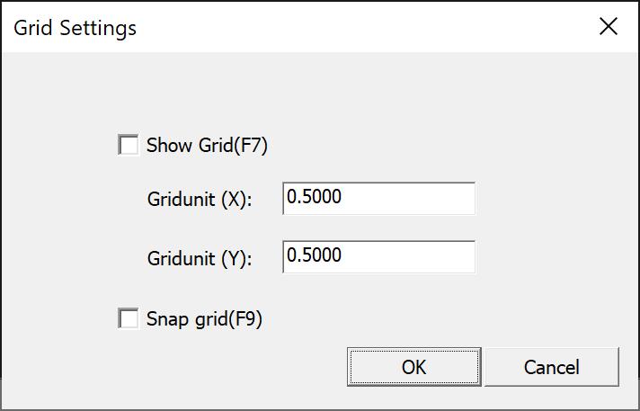
The GRID command in DWGSeeCAD opens the Grid Settings dialog for configuring the display and snap behaviour of the drawing grid. You can toggle grid visibility, set X and Y grid spacing, and enable grid snap. Shortcut keys F7 for Show Grid and F9 for Snap Grid are supported. This command helps you draw with regular spacing and precise alignment.
Command Prompt Workflow #

  1. Enter GRID on the command line and press Enter.
  2. The Grid Settings dialog pops up with the following options:
    • Show Grid(F7): Check to display the background grid; uncheck to hide it.
    • Gridunit (X): Set the horizontal spacing of grid lines.
    • Gridunit (Y): Set the vertical spacing of grid lines.
    • Snap grid(F9): Check to enable snap to grid points.
  3. Adjust parameters as required, then click OK to apply settings, or Cancel to discard changes.

Dialog Options #

  • Show Grid(F7): Toggle grid display. Press F7 as a quick toggle shortcut.
  • Gridunit (X): Horizontal grid spacing value.
  • Gridunit (Y): Vertical grid spacing value.
  • Snap grid(F9): Enable snapping cursor to grid intersections. Press F9 for quick toggle.
  • OK: Save and activate the grid configuration.
  • Cancel: Close the dialog without saving changes.

Usage Notes #

  • Grid is a visual reference aid and does not print with the drawing.
  • Grid snap restricts cursor movement to grid intersections for uniform drafting.
  • X and Y grid units can be set independently for rectangular grid layouts.

Application Scenarios #

Use GRID for schematic layout, part sketching, or drawing that requires evenly spaced features. It is ideal for electrical diagrams, cabinet layouts, fixture drawings and other tasks where regular alignment is needed.

Grid

Share This Article :

  • Facebook
  • X
  • LinkedIn
  • Pinterest
Table of Contents
  • GRID
    • Overview
    • Command Prompt Workflow
    • Dialog Options
    • Usage Notes
    • Application Scenarios

© 2026 DWGSee CAD Support

  • Home
  • Download
  • Articles
  • User Guide
  • Contact