Skip to content

DWGSee CAD Support

  • Home
  • Download
  • Articles
  • User Guide
  • Contact
DWGSee CAD Support

What's New

7
  • New Features in DWGSee CAD 2027
    • Aligh entities
    • Extract Dimension
    • SCRIPT
    • UNION(Command)
    • SUBTRACT (Command)
    • MASSPROP
    • Rename

Get Started

4
  • Command Line List
  • Main Features
  • System Requirements
  • Welcome to DWGSee CAD

Have You Tried?

6
  • How to Extract Dimensions from Engineering Drawings
  • How to isolate objects
  • How to use Design Center in DWGSee CAD
  • How to merge lines/arcs to one ployline
  • How to Draw Arrows in DWGSee CAD
  • How to Select Objects Based on Shared Properties?

User Guide

117
  • User Interface
    • GRID
  • Manage Drawing Files
    • Ucsicon
    • ISOLATEOBJECTS (Command)
    • UNISOLATEOBJECTS (Command)
    • HIDEOBJECTS (Command)
    • Units
    • Create a new drawing
  • Create Objects
    • BLEND
    • Hatch
    • Ellipse
    • Circle
    • Multiline
    • Spline
    • Point
    • XLINE
    • UNION(Command)
    • SUBTRACT (Command)
    • INTERSECT(Command)
    • Arc
    • Rectangle
    • Polygon
    • Polyline
    • Line
    • Create Text
      • TEXTABOVELINE
      • ARCTEXT
      • STYLE
    • Create Curved and Closed Geometry
      • SOLID
      • About Donuts
        • Donut
      • About Regions
        • Region
    • Create Linear and Reference Geometry
      • ExLine
      • MLSTYLE
      • TangentLine
  • Reference External Files and Data
    • ADCENTER
    • InsFromDWG
    • INSBLKDESIGNBIND
    • DWFATTACH
  • Defining Blocks
    • STATBLK
    • WBLOCK
    • About Purging Unreferenced Layers, Blocks, and Style Definitions
      • PURGE
  • Modify Objects
    • DIMSYMDRIVER
    • SHAFTUNDERCUT
    • HOLEUNDERCUT
    • HOLECHAMFER
    • SHAFTCHAMFER
    • BLKREPLACE
    • TXTEXP
    • IMAGECLIP
    • VPCLIP
    • LINESTOPL
    • DCANGULAR
    • DIMALIGN
    • DIMOBLIQUE
    • DIMDRIVER
    • CHAMFER
    • EXTEND
    • TRIM
    • Pedit
    • Mledit
    • Fillet
    • Copy
    • Scale
    • Array
    • Mirror
    • PURGE
    • Duplicate and Array Objects
      • Patharray
      • Offset
      • About Copying Objects
        • NCOPY(Command)
    • Remove Objects and Object Segments
      • Erase
      • Break
      • Join
      • About Correcting Mistakes
        • Overkill
        • OOPS
    • Change General Object Properties
      • SELECTSIMILAR
      • CANNOSCALE
      • Draw order
      • Linetype
      • Layer
      • How to Change the Color of Selected Objects?
      • LIST
      • About Object Properties
        • MATCHPROP
    • Editing Complex Objects
      • XCLIP
      • DDPTYPE
      • EDITTOL
      • EXPLODE
    • Change the Size and Length of Objects
      • Lengthen
      • EXTEND
      • TRIM
    • Move and Rotate Objects
      • Aligh entities
      • Align
      • Rotate
      • Stretch
      • Move
  • Control Drawing Views
    • REGEN
    • ZOOM
    • PAN
  • Control Precision with Drafting Aids
    • SNAP
    • LIMITS (Command)
  • Add Hatches, Fills, Tables, and Revision Clouds
    • GRADIENT
    • Wipeout
  • Create Notes, Labels, and Leaders
    • TEXTALIGN
    • Extract Dimension
    • ANNOALLVISIBLE (System Variable)
  • Dimension Objects
    • DIMCHAMFER
    • SCALEPART
    • REVC
    • DIMSTYLE
    • DIMCONTINUE
    • DIMJOGGED
    • NUMBER
    • DIMALIGNED
    • DIMBASELINE
    • TOLERANCE
    • CenterLine
  • Tools
    • STATBLK
    • STATTBLK
    • Extract table
    • PLDATA

License

1
  • End-User License Agreement
View Categories
  • DWGSee CAD
  • Support
  • User Guide
  • Tools
  • STATTBLK

STATTBLK

0:00 / 1:43

STATTBLK #

Overview #

In DWGSeeCAD, the STATTBLK command generates and inserts a statistical table for selected attribute blocks. After running the command, you select target attribute blocks, then the Select output Tags dialog opens. You can choose which attribute tags to export, fill in their values, adjust layout and text height, and finally place the completed attribute table at a specified point on the drawing.
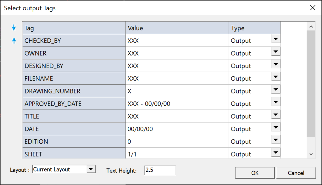
Dialog Settings #

  • Tag: The name of the block attribute field, such as CHECKED_BY, OWNER, DESIGNED_BY, FILENAME, DRAWING_NUMBER, TITLE, DATE, EDITION, SHEET.
  • Value: Custom content or placeholder value for each attribute tag, which will display in the output table.
  • Type: Sets the output type for each tag entry.
  • Layout: Select the target layout for table insertion; the default is Current Layout.
  • Text Height: Define the text height of the content inside the generated table.

Command Workflow #

  1. Enter STATTBLK in the command line and press Enter.
  2. Select the attribute blocks you want to count and collect attributes from.
  3. The Select output Tags dialog pops up, configure required tags, values and table style parameters.
  4. Click OK, then pick a position on the drawing to place the finished statistics table.

Usage Notes #

  • STATTBLK only works with attribute blocks. Ordinary blocks without attributes cannot be read for this table.
  • You can adjust the order of tags using the up/down arrow buttons on the left side of the dialog.
  • All configured tag information will be exported into the table at the selected insertion location.
  • Modify Text Height before confirming to control the readability of table text on the drawing.

Application Scenarios #

Use STATTBLK to create title block summaries, part lists, component schedules, drawing revision logs and attribute statistics tables for assembly drawings, electrical schematics and engineering layout drawings. It helps quickly extract and organize attribute information from multiple attribute blocks into a neat table directly on the DWG.

Block table

Share This Article :

  • Facebook
  • X
  • LinkedIn
  • Pinterest
Table of Contents
  • STATTBLK
    • Overview
    • Dialog Settings
    • Command Workflow
    • Usage Notes
    • Application Scenarios

© 2026 DWGSee CAD Support

  • Home
  • Download
  • Articles
  • User Guide
  • Contact