Skip to content

DWGSee CAD Support

  • Home
  • Download
  • Articles
  • User Guide
  • Contact
DWGSee CAD Support

What's New

7
  • New Features in DWGSee CAD 2027
    • Aligh entities
    • Extract Dimension
    • SCRIPT
    • UNION(Command)
    • SUBTRACT (Command)
    • MASSPROP
    • Rename

Get Started

4
  • Command Line List
  • Main Features
  • System Requirements
  • Welcome to DWGSee CAD

Have You Tried?

6
  • How to Extract Dimensions from Engineering Drawings
  • How to isolate objects
  • How to use Design Center in DWGSee CAD
  • How to merge lines/arcs to one ployline
  • How to Draw Arrows in DWGSee CAD
  • How to Select Objects Based on Shared Properties?

User Guide

117
  • User Interface
    • GRID
  • Manage Drawing Files
    • Ucsicon
    • ISOLATEOBJECTS (Command)
    • UNISOLATEOBJECTS (Command)
    • HIDEOBJECTS (Command)
    • Units
    • Create a new drawing
  • Create Objects
    • BLEND
    • Hatch
    • Ellipse
    • Circle
    • Multiline
    • Spline
    • Point
    • XLINE
    • UNION(Command)
    • SUBTRACT (Command)
    • INTERSECT(Command)
    • Arc
    • Rectangle
    • Polygon
    • Polyline
    • Line
    • Create Text
      • TEXTABOVELINE
      • ARCTEXT
      • STYLE
    • Create Curved and Closed Geometry
      • SOLID
      • About Donuts
        • Donut
      • About Regions
        • Region
    • Create Linear and Reference Geometry
      • ExLine
      • MLSTYLE
      • TangentLine
  • Reference External Files and Data
    • ADCENTER
    • InsFromDWG
    • INSBLKDESIGNBIND
    • DWFATTACH
  • Defining Blocks
    • STATBLK
    • WBLOCK
    • About Purging Unreferenced Layers, Blocks, and Style Definitions
      • PURGE
  • Modify Objects
    • DIMSYMDRIVER
    • SHAFTUNDERCUT
    • HOLEUNDERCUT
    • HOLECHAMFER
    • SHAFTCHAMFER
    • BLKREPLACE
    • TXTEXP
    • IMAGECLIP
    • VPCLIP
    • LINESTOPL
    • DCANGULAR
    • DIMALIGN
    • DIMOBLIQUE
    • DIMDRIVER
    • CHAMFER
    • EXTEND
    • TRIM
    • Pedit
    • Mledit
    • Fillet
    • Copy
    • Scale
    • Array
    • Mirror
    • PURGE
    • Duplicate and Array Objects
      • Patharray
      • Offset
      • About Copying Objects
        • NCOPY(Command)
    • Remove Objects and Object Segments
      • Erase
      • Break
      • Join
      • About Correcting Mistakes
        • Overkill
        • OOPS
    • Change General Object Properties
      • SELECTSIMILAR
      • CANNOSCALE
      • Draw order
      • Linetype
      • Layer
      • How to Change the Color of Selected Objects?
      • LIST
      • About Object Properties
        • MATCHPROP
    • Editing Complex Objects
      • XCLIP
      • DDPTYPE
      • EDITTOL
      • EXPLODE
    • Change the Size and Length of Objects
      • Lengthen
      • EXTEND
      • TRIM
    • Move and Rotate Objects
      • Aligh entities
      • Align
      • Rotate
      • Stretch
      • Move
  • Control Drawing Views
    • REGEN
    • ZOOM
    • PAN
  • Control Precision with Drafting Aids
    • SNAP
    • LIMITS (Command)
  • Add Hatches, Fills, Tables, and Revision Clouds
    • GRADIENT
    • Wipeout
  • Create Notes, Labels, and Leaders
    • TEXTALIGN
    • Extract Dimension
    • ANNOALLVISIBLE (System Variable)
  • Dimension Objects
    • DIMCHAMFER
    • SCALEPART
    • REVC
    • DIMSTYLE
    • DIMCONTINUE
    • DIMJOGGED
    • NUMBER
    • DIMALIGNED
    • DIMBASELINE
    • TOLERANCE
    • CenterLine
  • Tools
    • STATBLK
    • STATTBLK
    • Extract table
    • PLDATA

License

1
  • End-User License Agreement
View Categories
  • DWGSee CAD
  • Support
  • User Guide
  • Modify Objects
  • HOLEUNDERCUT

HOLEUNDERCUT

0:00 / 1:39

HOLEUNDERCUT #

Overview #

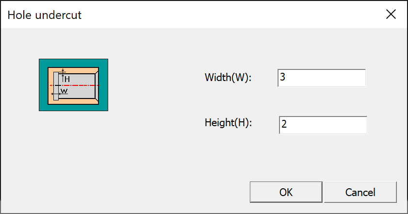
The HOLEUNDERCUT command in DWGSeeCAD creates internal undercut groove geometry for holes. A dedicated Hole undercut dialog box is provided, with a preview schematic for setting groove Width(W) and Height(H). It is a DWGSeeCAD exclusive extended command for machining relief grooves inside rotary holes.
Command Prompt Workflow #

  1. Enter HOLEUNDERCUT on the command line and press Enter.
  2. Prompt: [Hole undercut ] Select shaft chamfering end face: Pick the end face of the hole to place the undercut groove.
  3. Prompt: [Hole undercut ] Select an outline of the turning surface: Select one inner profile line of the rotary hole surface.
  4. Prompt: [Hole undercut ] Select another outline of the turning surface: Select the opposite inner profile line of the rotary hole surface.
  5. The Hole undercut dialog opens:
    • Width(W): Input the axial width of the undercut relief groove.
    • Height(H): Input the radial depth of the undercut relief groove.
  6. Click OK to generate the undercut geometry; click Cancel to abandon the operation.

Dialog Options #

  • Width(W): Axial width of the internal hole undercut groove.
  • Height(H): Radial depth of the undercut groove, measured from the hole inner wall.
  • OK / Cancel: Confirm and create the hole undercut, or close the dialog without saving changes.

Usage Notes #

  • HOLEUNDERCUT is used to generate internal relief undercut grooves inside holes, different from HOLECHAMFER which creates hole chamfer geometry.
  • It requires selecting the hole end face plus two opposite turning outlines to identify the rotary hole geometry.
  • Width and height parameters comply with standard machining undercut groove specifications for internal holes.
  • This is a custom DWGSeeCAD extended command and is not built into native AutoCAD.

Application Scenarios #

Use HOLEUNDERCUT for internal thread relief grooves, grinding undercuts and tool escape grooves of machined holes. It quickly generates accurate undercut geometry for mechanical manufacturing drawings.

Share This Article :

  • Facebook
  • X
  • LinkedIn
  • Pinterest
Table of Contents
  • HOLEUNDERCUT
    • Overview
    • Command Prompt Workflow
    • Dialog Options
    • Usage Notes
    • Application Scenarios

© 2026 DWGSee CAD Support

  • Home
  • Download
  • Articles
  • User Guide
  • Contact