HOLECHAMFER #
Overview #
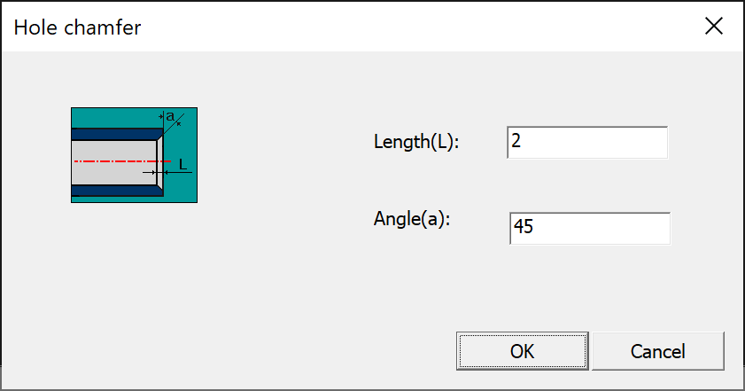
The HOLECHAMFER command in DWGSeeCAD creates chamfer geometry for internal hole features. A dedicated Hole chamfer dialog box is provided, with a preview schematic for setting chamfer Length(L) and Angle(a). It is a DWGSeeCAD exclusive extended command, specially designed for internal rotary hole chamfering in mechanical drawings.
Command Prompt Workflow #
- Enter HOLECHAMFER on the command line and press Enter.
- Prompt: [Hole chamfer ] Select hole chamfering end face: Pick the end face of the hole for chamfer creation.
- Prompt: [Hole chamfer ] Select an outline of the turning surface: Select one inner profile line of the rotary hole surface.
- Prompt: [Hole chamfer ] Select another outline of the turning surface: Select the opposite inner profile line of the rotary hole surface.
- The Hole chamfer dialog opens:
- Length(L): Input the axial length of the hole chamfer.
- Angle(a): Input the chamfer angle relative to the hole centerline.
- Click OK to generate the chamfer geometry; click Cancel to abandon the operation.
Dialog Options #
- Length(L): Axial length dimension of the internal hole chamfer.
- Angle(a): Chamfer angle between the chamfer slope and the hole centerline.
- OK / Cancel: Confirm and create the hole chamfer, or close the dialog without saving changes.
Usage Notes #
- HOLECHAMFER generates chamfer geometry for inner holes, while SHAFTCHAMFER is used for external shaft chamfers.
- It requires selecting the hole end face plus two opposite turning outlines to identify the rotary hole geometry.
- Length and angle parameters comply with standard mechanical hole chamfer specifications.
- This is a custom DWGSeeCAD extended command and is not built into native AutoCAD.
Application Scenarios #
Use HOLECHAMFER for through holes, counterbore holes, stepped holes and other machined internal rotary features. It quickly generates accurate hole chamfer geometry for mechanical manufacturing drawings.


